Site Identification:
MIT Campus:

Figure 1.1: Map of the MIT Campus, existing Chiller Loop buildings (blue), analyzed borehole data (red).[1][3]
MIT campus is ideal for deploying a geothermal heating and cooling system:
- The campus encompasses 168 acres with more than 40 gardens and green spaces.
- All heating and cooling HVAC energy is currently provided in a Central Utilities Plant (CUP) by natural gas powered Combined Heat and Power (CHP) and boilers plus chillers.
Our proposed Geothermal District Heating and Cooling (GDHC) system would accelerate MIT’s decarbonization to about 2035 at likely less net cost and 15 years ahead of their schedule. Even further, converting to a GDHC system could be over 40% paid for through the Inflation Reduction Act (IRA) Tax Credits and Massachusetts State Tax incentives for renewable energy and energy efficiency making a GDHC system almost certainly far more cost-efficient than any other decarbonization approach.
Justification of Site
- 97% of Scope 1 emissions are from natural gas CHP-based CUP plant and regional electric grid emissions.
- A GDHC system will leverage the consistent ground temperatures to provide the most efficient heating and cooling, eliminate direct carbon emissions, and eventually all emissions once the connected regional grid is clean power.
Geothermal Resource Assessment
History, Geography, Topography of Site:
- Historic maps indicate the area now occupied by the MIT Campus was previously Charles River Basin marshland. By 1899, the land under MIT was filled for site development with silt, sand, gravel, ashes, and other city waste.
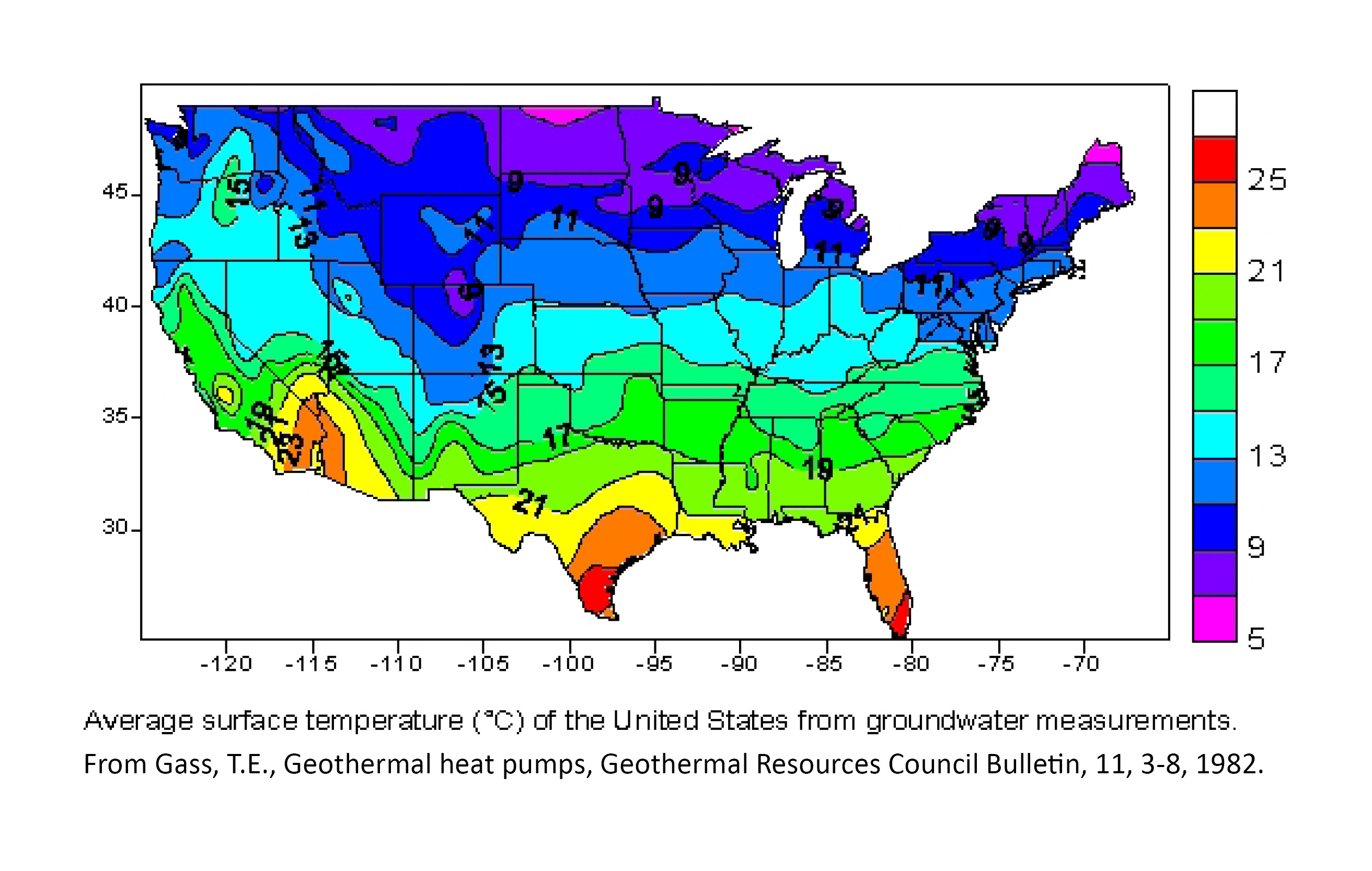
- The physical geology of Cambridge dates the Boston Basin from the Cambrian to Proterozoic Z era and comprises pelitic rock. The Undisturbed Ground Temperature is about 51.5°F.
- Numerous geotechnical reports and an MIT-commissioned study confirm the underlying bedrock is Cambridge Argillite and the overburden is mostly Boston Marine Clay to over 100’.
- The clay deposits are fully saturated (adjacent dammed river) and mostly soft with some sand and little competent rock or gravel, providing excellent thermal exchange and low-cost drilling.
- This soil likely has a reliable Heat Capacity (HC) = 62 BTU/(cuft * °F) and a Thermal Conductivity (BTU/ft-hr-°F) of just under 1.0 – an Advanced Thermal Conductivity Test will be required to determine the precise figures.
- Deeper geothermal drilling at the Moderna building just NE of MIT showed the Argillite is very fragile, requiring special, more expensive drilling techniques.
Conversion to GDHC System:
- Implementing a GDHC requires water source heat pump installation, ground loop installation, and a water distribution system termed an “Ambient Loop” in 5th Generation and later district systems.
- Existing Steam and CW distribution piping runs throughout MIT’s campus. The existing CW piping loop can be directly “transitioned” into an Ambient Loop for a GDHC – the only difference between a CW Loop and an Ambient Loop is the expected temperature range, 45°-54°F for a CW Loop relaxed to 40°-90°F for an Ambient Loop.
- New piping is one of the largest GDHC expenses, so utilizing the existing infrastructure drastically reduces implementation costs.
Novel Ground Heat Exchanger (GHEX) and Thermal Battery Installation Techniques:

Figure 2.3 Innovative Thermal Battery and Ground Heat Exchanger (GHEX) Installation Techniques
- Our team has identified novel installation techniques for low-impact ground loop installation based on MIT’s local geology and campus density.
- Common overburden Directional Boring techniques will allow careful GHEX placement under most of the campus, with “sensor loops” and special thermal pattern management used in thermally sensitive areas such as under building pilings.
- ORNL-designed Thermal Batteries will be installed as needed, using techniques currently under development that require only 20 sq ft surface space free of buried utilities.
- The fully saturated soft clay and sedimentary soils under MIT’s campus readily support these techniques for areas from 50’-100’ deep.
- The approach, validated by geothermal heat pump industry experts, provides predictable thermal conductivity and reduces the GHEX size needed.
- Large drilling equipment is not required with soft soils for a surface area under a 20’ radius, with a limited number of locations required to bore the whole campus.
- Star pattern Inclined Drilling techniques, pioneered by Celsius Energy, use simultaneous casing rigs suitable for the soft Argillite bedrock formations to drill deeper bores if needed. To confirm the approach, a test bore is needed due to the fragile bedrock.
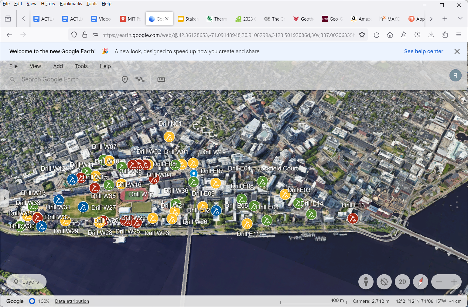
Figure 2.4 Drill Sites Map for Inclined Drilling site, coded by size & access (interactive map link: [11])
A Google Map with site photos showing 51 drill sites that meet the larger minimum ~20’ x 50’ work areas that Celsius Energy requires is shown in Figure 2.4.[11] Both drilling approaches are highly compatible with the urban setting and the need to minimize disruption to campus activities, with directional drilling fitting virtually everywhere on campus.
Available GHEX Size:
- Combining all the above and assuming we can only use the bottom 50’ of the >100’ deep overburden under buildings (adding 10’ to include the expected below areas thermal coupling), and further assuming a 20°F annual GHEX ground temperature charge/discharge, we calculate a Thermal Storage capability of the lower 168 acres to be 168A * 43560 sqft/A * 60’ * 20°F * 62 BTU/(cuft * °F) = 544,465 MBTU (million BTUs).
- Per the data we have, MIT consumes about 230,000 MBTU after adjusting for the anticipated recovery of exhaust energy, anticipated diversity savings, and adjusting for heat pumps operating at COP=4.
- Under the proposed upgrades, only 42% of GHEX available space is required (230K/544K) to achieve full annual thermal storage for a GDHC system under MIT’s current load.
- Required space will likely decline once a detailed numerical model is built and analyzed.
Geothermal Boring Planned:
- The GHEX plan based on directional boring would use ~1.5M feet of bore (15’ spacing), or about 580 feet of bore per day given the 12-year optimal installation plan.
- To cover all contingencies, including weather and campus activities, we expect a 3 site continuous boring plan to be implemented.
- The small bore sites will be easily hidden, low decibel level, with support equipment (mud cleaning, etc) at the closest available open space with road access. Only small rigs will be used and all areas can be fully restored.
- To avoid underground utility installations, directional boring will be used to connect each vault/drill site to nearby buildings and the Ambient Loop, avoiding trenching.
Conclusions:
- MIT’s fully saturated overburden soils are ideal for a reliable, low-cost, and lowest possible impact ground heat exchanger.
- The existing campus two-pipe CW loop can be easily transitioned to Ambient Loop GDHC and directional boring techniques can be used to avoid typical GDHC trenching operations.
- Thermal Batteries and directional bored GHEX can be readily installed in these soils.
- Our analysis shows there is plenty of GHEX space available in the overburdened soils specifically because they are fully saturated.
- The Thermal Batteries benefit from the saturated soil’s reliable thermal conductivity for additional capacity to store energy when grid power costs are low and use the energy to lower HVAC loads when grid power costs are high
- . The approach represents 6th Generation GDHC, the most advanced we could identify.
Next Steps:
- “Design” of a GDHC always requires full system “digital twin” modeling and experimentation with the various elements and GHEX size.
- The modeling will be used to confirm the proposed design before committing to engineering and construction and for detailed costing analysis to meet financial targets.
- This next step is underway now at MIT, and will shortly include the additional findings we have made and reported here.
References:
[1] Zen, E. -an et al. Bedrock Geologic Map of Massachusetts. USGS Unnumbered Series (1983). at <http://ngmdb.usgs.gov/Prodesc/proddesc_16357.htm>
[2] Gass, T.E., Geothermal heat pumps, Geothermal Resources Council Bulletin, 11, 3-8, 1982 (scan)
[3] Local Climatological Data Station Details, U.S. NOAA National Centers for Environmental Information, Logan Airport https://www.ncdc.noaa.gov/cdo-web/datasets/LCD/stations/WBAN:14739/detail
[4] Multiple Geotechnical Bore Reports by Hailey and Aldrich including FIle No’s 113856-003, 135155-004, 134283-002, obtained from MA public records
[5] Haley & Aldrich. MIT Geothermal Evaluation. 2011
[6] Advanced Testing Method for Ground Thermal Conductivity, ORNL/TM-2017/208, Liu, Clemenzi
[7] MIT Office of Sustainability, url https://sustainability.mit.edu/tab/energy
[8] MIT Sustainability Datapool, url https://datapool.mit.edu/ (data is behind a firewall)
[9] Dual Source HP Sys With Thermal Energy Storage, Xiaobing Liu, Geothermal Rising Conf. San Diego, CA. Oct. 3-6, 2021. p. 5
[10] Celsius Energy Star Pattern Inclined Drilling, url: https://www.celsiusenergy.com/en/our-solution/[11] Google-based Drill Sites Map showing areas large enough for larger Inclined Drilling
[11] MIT Office of Sustainability. url: https://sustainability.mit.edu/topic/zero-carbon-campus
[12] ISO New England “Real-Time Energy Offer Data”, link
[13] Drilling site overlay source: MA Energy & Environmental Affairs Reportable Releases, link